K3HB-R
Rotary Pulse Indicator
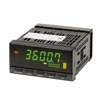
Digital Rotary Pulse Meter Capable of 50 kHz Measurements
Related Contents
- Features
- Lineup
- Specifications
- Dimensions
- Catalog / Manual / CAD / Software
last update: July 1, 2026
Ratings
| Supply voltage | 100 to 240 VAC, 24 VAC/VDC | |
|---|---|---|
| Allowable power supply voltage
range |
85% to 110% of the rated power supply voltage | |
| Power consumption *1 | 100 to 240 VAC: 18 VA max. (max. load)
24 VAC/DC: 11 VA/7 W max. (max. load) |
|
| Input | No-voltage contact, voltage pulse, open collector | |
| External power supply | 12 VDC ±10%, 80 mA (models with external power supply only) | |
| Event
inputs *2 |
Startup compensation
timer input |
NPN open collector or no-voltage contact signal
ON residual voltage: 2 V max. ON current at 0 Ω: 4 mA max. Max. applied voltage: 30 VDC max. OFF leakage current: 0.1 mA max. |
| Hold input | ||
| Reset input | ||
| Bank input | ||
| Output
ratings (depends on the model) |
Relay output | 250 VAC, 30 VDC, 5 A (resistive load)
Mechanical life expectancy: 5,000,000 operations (UL not applicable), Electrical life expectancy: 50,000 operations |
| Transistor output | Maximum load voltage: 24 VDC, Maximum load current: 50 mA, Leakage current:
100 μ A max. |
|
| Linear output | Linear output 0 to 20 mA DC, 4 to 20 mA DC:
Load: 500 Ω max, Resolution: Approx. 10,000, Output error: ±0.5% FS Linear output 0 to 5 VDC, 1 to 5 VDC, 0 to 10 VDC: Load: 5 kΩ max, Resolution: Approx. 10,000, Output error: ±0.5% FS (1 V or less: ±0.15 V; no output for 0 V or less) |
|
| Display method | Negative LCD (backlit LED) display
7-segment digital display (Character height: PV: 14.2 mm (green/red); SV: 4.9 mm (green)) |
|
| Main functions | Scaling function, measurement operation selection, averaging, output hysteresis,
output OFF delay, output test, teaching, display value selection, display color selection, key protection, bank selection, display refresh period, maximum/ minimum hold, reset |
|
| Ambient operating temperature *3 | - 10 to 55 °C (with no icing or condensation) | |
| Ambient operating humidity | 25% to 85% | |
| Storage temperature | - 25 to 65 °C (with no icing or condensation) | |
| Altitude | 2,000 m max. | |
| Accessories | Watertight packing, 2 fixtures, terminal cover, unit stickers, instruction manual. | |
*1. DC power supply models require a control power supply capacity of approximately 1 A per Unit when power is turned
ON. Particular attention is required when using two or more DC power supply models. The OMRON S8VS-series DC
Power Supply Unit is recommended.
*2. PNP input types are also available.
*3. Use models with relay output (C2) at an ambient temperature of 50°C or lower.
Characteristics
| Display range | - 19,999 to 99,999 | |
|---|---|---|
| Measurement accuracy
(at 23±5 °C) |
Functions F1, F6: ±0.006% rgd ±1 digit (for voltage pulse/open collector sensors)
Functions F2 to F5: ±0.02% rgd ±1 digit (for voltage pulse/open collector sensors) |
|
| Measurement range | Functions F1 to F6: 0.5 mHz to 50 kHz (for voltage pulse/open collector sensors) | |
| Input signals | Contact input (dry contact input) (30-Hz max. with ON/OFF pulse width of 15 ms min.)
No contact voltage pulse (50-KHz max. with ON/OFF pulse width of 9 µs min.; ON voltage: 4.5 to 30 V; OFF voltage: - 30 to 2 V; input impedance: 10 kΩ ) Open collector (50-KHz max. with ON/OFF pulse width of 9 µs min.) |
|
| Connectable sensors | ON residual voltage: 3 V max.
OFF leakage current: 1.5 mA max. Load current: Must have a switching capacity of 20 mA or higher. Must be able to properly switch load currents of 5 mA or less. |
|
| Comparative output
response time (transistor output) |
Functions F1 to F6: 100 ms max. (time until the comparative output is made when there is a
forced sudden change in the input signal from 15% to 95% or 95% to 15%.) |
|
| Linear output response
time |
Functions F1 to F6: 110 ms max. (time until the final analog output value is reached when
there is a forced sudden change in the input signal from 15% to 95% or 95% to 15%.) |
|
| Insulation resistance | 20 MΩ min. (at 500 VDC) | |
| Dielectric strength | 2,300 VAC for 1 min between external terminals and case | |
| Noise immunity | 100 to 240 VAC models: ± 1,500 V at power supply terminals in normal or common mode
(waveform with 1-ns rising edge and pulse width of 1 μs/100 ns) 24 VAC/VDC models: ± 1,500 V at power supply terminals in normal or common mode (waveform with 1-ns rising edge and pulse width of 1 μs/100 ns) |
|
| Vibration resistance | Frequency: 10 to 55 Hz; Acceleration: 50 m/s2, 10 sweeps of 5 min each in X, Y, and Z
directions |
|
| Shock resistance | 150 m/s2 (100 m/s2 for relay outputs) 3 times each in 3 axes, 6 directions | |
| Weight | Approx. 300 g (Base Unit only) | |
| Degree of protection
(UL not applicable) |
Front panel | Conforms to NEMA 4X for indoor use (equivalent to IP66) |
| Rear case | IP20 | |
| Terminals | IP00 + finger protection (VDE0106/100) | |
| Memory protection | EEPROM (non-volatile memory)
Number of rewrites: 100,000 |
|
| Applicable standards * | UL/CSA 61010-1, UL/CSA 61010-2-030
EN/IEC 61010-1, EN/IEC 61010-2-030 Pollution degree 2/Overvoltage category II EN61326-1 |
|
| EMC | EMI: EN61326-1 Industrial electromagnetic environment
Electromagnetic radiation interference: CISPR 11 Group 1, Class A Terminal interference voltage: CISPR 11 Group 1, Class A EMS: EN61326-1 Industrial electromagnetic environment Electrostatic Discharge Immunity: EN61000-4-2: 4 kV (contact), 8 kV (in air) Radiated Electromagnetic Field Immunity: EN61000-4-3: 10 V/m 1 kHz sine wave amplitude modulation (80 MHz to 1 GHz, 1.4 to 2 GHz) Electrical Fast Transient/Burst Noise Immunity: EN61000-4-4: 2 kV (power line), 1 kV (I/O signal line) Surge Immunity: EN61000-4-5: 1 kV with line (power line), 2 kV with ground (power line) Conducted Disturbance Immunity: EN61000-4-6: 3 V (0.15 to 80 MHz) Power Frequency Magnetic Immunity: EN61000-4-8: 30 A/m (50 Hz) continuous time Voltage Dips and Interruptions Immunity: EN61000-4-11: 0.5 cycle, 0 ° /180 °, 100% (rated voltage) |
|
* Models equipped with relay output (C2) are cURus certified.
last update: July 1, 2026