CJ1W-PA / PD
CJ-series Power Supply Unit
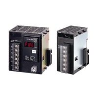
Equipped with the RUN output for checking the operation status, as well as the replacement notification function for easy maintenance. Lineup of five models including the AC power supply (25W).
Related Contents
- Features
- Lineup
- Specifications
- Dimensions
- Catalog / Manual / CAD / Software
last update: July 1, 2021
| Item | Specifications | ||
|---|---|---|---|
| Model | CJ1W-PA205R | CJ1W-PA205C | CJ1W-PA202 |
| Supply voltage | 100 to 240 V AC (wide-range), 50/60 Hz | ||
| Operating voltage and
frequency ranges |
85 to 264 V AC, 47 to 63 Hz | ||
| Power consumption | 100 VA max. | 50 VA max. | |
| Inrush current *1 | At 100 to 120 V AC: 15 A/8 ms max. for cold start at room
temperature At 200 to 240 V AC: 30 A/8 ms max. for cold start at room temperature |
At 100 to 120 V AC:
20 A/8 ms max. for cold start at room temperature At 200 to 240 V AC: 40 A/8 ms max. for cold start at room temperature |
|
| Output capacity *7 | 5.0 A, 5 V DC (including supply to CPU Unit) | 2.8 A, 5 V DC
(including supply to CPU Unit) |
|
| 0.8 A, 24 V DC | 0.4 A, 24 V DC | ||
| Total: 25 W max. | Total: 14 W max. | ||
| Output terminal
(service supply) |
Not provided. | ||
| RUN output *2 | Contact configuration:
SPST-NO Switch capacity: 250 V AC, 2 A (resistive load) 120 V AC, 0.5 A (inductive load), 24 V DC, 2A (resistive load) 24 V DC, 2 A (inductive load) |
Not provided. | |
| Replacement
notification function |
Not provided. | With Alarm output (open-
collector output) 30 V DC max., 50 mA max. |
Not provided. |
| Insulation resistance | 20 MΩ min. (at 500 V DC)
between AC external and GR terminals *3 |
20 MΩ min. (at 500 V DC)
between all external terminals and GR terminal *3, and between all alarm output terminals. 20 MΩ 1 min. (at 250 V DC) between all alarm output terminals and GR terminal *3. |
20 MΩ min. (at 500 V DC)
between AC external and GR terminals *3 |
| Dielectric strength *4 | 2,300 V AC 50/60 Hz for 1 min
between AC external and GR terminals *3 Leakage current: 10 mA max. |
2,300 VAC, 50/60 Hz for 1 min
between all external terminals and GR terminal *3 and between all alarm output terminals with a leakage current of 10 mA max. 1,000 V AC, 50/60 Hz for 1 min between all alarm output terminals and GR terminal *3 with a leakage current of 10 mA max. |
2,300 V AC 50/60 Hz for 1 min
between AC external and GR terminals *3 Leakage current: 10 mA max. |
| 1,000 V AC, 50/60 Hz for 1 minute between DC external and GR terminals *3
Leakage current: 10 mA max. |
|||
| Noise immunity | 2 kV on power supply line (conforming to IEC61000-4-4) | ||
| Vibration resistance | Conforms to IEC60068-2-6
5 to 8.4 Hz with 3.5-mm amplitude, 8.4 to 150 Hz Acceleration of 9.8 m/s2 for 100 min in X, Y, and Z directions (10 sweeps of 10 min each = 100 min) |
||
| Shock resistance | Conforms to IEC60068-2-27
147 m/s2, 3 times in X, Y, and Z directions (100 m/s2 for Relay Output Units) |
||
| Ambient operating
temperature |
0 to 55 °C | ||
| Ambient operating
humidity |
10% to 90% (with no
condensation) |
10% to 90% (with no
condensation) *5 |
10% to 90% (with no
condensation) |
| Atmosphere | Must be free from corrosive gases. | ||
| Ambient storage
temperature |
- 20 to 70 °C (excluding
battery) |
- 20 to 75 °C *5 | - 20 to 75 °C (excluding
battery) |
| Grounding | Less than 100 Ω | ||
| Enclosure | Mounted in a panel. | ||
| Weight | 350 g max. | 400 g max. | 200 g max. |
| CPU Rack
dimensions |
90.7 to 466.7 × 90 × 65 mm (W × H × D) (not including cables)
Note: W = a + b + 20 × n + 31 × m + 14.7 a: Power Supply Unit: PA205R and PA205C = 80; PA202 = 45; PD025 = 60; PD022=27 b: CPU Unit: CJ1-H or CJ1 = 62; CJ1M-CPU1[] = 31 *8; CJ1M-CPU2[] = 49 *8 The total width is given by the following: W = 156.7 + n × 20 + m × 31, where n is the number of 32-point I/O Units or I/O Control Units and m is the number of other Units. |
||
| Safety measures | Conforms to cULus and EC Directives. | ||
| Item | Specifications | |
|---|---|---|
| Model | CJ1W-PD025 | CJ1W-PD022 |
| Supply voltage | 24 VDC | |
| Operating voltage and
frequency ranges |
19.2 to 28.8 V DC | 21.6 to 26.4 V DC |
| Power consumption | 50 W max. | 35 W max. |
| Inrush current *1 | At 24 V DC: 30 A/20 ms max. for cold start | |
| Output capacity *7 | 5.0 A, 5 V DC (including supply to CPU Unit) | 2.0 A, 5 V DC (including supply to CPU Unit) |
| 0.8 A, 24 V DC | 0.4 A, 24 V DC | |
| Total: 25 W max. | Total: 19.6 W max. | |
| Output terminal
(service supply) |
Not provided. | |
| RUN output *2 | Not provided. | |
| Replacement
notification function |
Not provided. | |
| Insulation resistance | 20 MΩ min. (at 500 V DC) between DC
external and GR terminals *3 |
---
*6 |
| Dielectric strength *4 | 1,000 V AC, 50/60 Hz for 1 min between DC
external and GR terminals *3 Leakage current: 10 mA max. |
---
*6 |
| Noise immunity | 2 kV on power supply line (conforming to IEC61000-4-4) | |
| Vibration resistance | Conforms to IEC60068-2-6
5 to 8.4 Hz with 3.5-mm amplitude, 8.4 to 150 Hz Acceleration of 9.8 m/s2 for 100 min in X, Y, and Z directions (10 sweeps of 10 min each = 100 min) |
|
| Shock resistance | Conforms to IEC60068-2-27
147 m/s2, 3 times in X, Y, and Z directions (100 m/s2 for Relay Output Units) |
|
| Ambient operating
temperature |
0 to 55 °C | |
| Ambient operating
humidity |
10% to 90% (with no condensation) | |
| Atmosphere | Must be free from corrosive gases. | |
| Ambient storage
temperature |
- 20 to 75 °C (excluding battery) | |
| Grounding | Less than 100 Ω | |
| Enclosure | Mounted in a panel. | |
| Weight | 335 g max. | 130 g max. |
| CPU Rack
dimensions |
90.7 to 466.7 × 90 × 65 mm (W × H × D) (not including cables)
Note: W = a + b + 20 × n + 31 × m + 14.7 a: Power Supply Unit: PA205R and PA205C = 80; PA202 = 45; PD025 = 60; PD022=27 b: CPU Unit: CJ1-H or CJ1 = 62; CJ1M-CPU1[] = 31 *8; CJ1M-CPU2[] = 49 *8 The total width is given by the following: W = 156.7 + n × 20 + m × 31, where n is the number of 32-point I/O Units or I/O Control Units and m is the number of other Units. |
|
| Safety measures | Conforms to cULus and EC Directives. | |
*1. Disconnect the Power Supply Units LG terminal from the GR terminal when testing insulation and dielectric strength.
Testing the insulation and dielectric strength with the LG terminal and the GR terminals connected will damage
internal circuits in the CPU Unit.
*2. Supported only when mounted to CPU Rack.
*3. The inrush current is given for a cold start at room temperature. The inrush control circuit uses a thermistor element
with a low-temperature current control characteristic. If the ambient temperature is high or the PLC is hot-started, the
thermistor will not be sufficiently cool, and the inrush currents given in the table may be exceeded by up to twice the
given values. When selecting fuses or breakers for external circuits, allow sufficient margin in shut-off performance.
*4. Maintain an ambient storage temperature of −25 to 30°C and relative humidity of 25% to 70% when storing the Unit for
longer than 3 months to keep the replacement notification function in optimum working condition.
*5. Change the applied voltage gradually using the adjuster on the Tester. If the full dielectric strength voltage is applied
or turned OFF using the switch on the Tester, the generated impulse voltage may damage the Power Supply Unit.
*6. CJ1W-PD022 is not insulated between the primary DC power and secondary DC power.
*7. Internal components in the Power Supply Unit will deteriorate or be damaged if the Power Supply Unit is used for an
extended period of time exceeding the power supply output capacity or if the outputs are shorted.
*8. Final order entry date for CJ1M :The end of March, 2021
Checking Current Consumption and Power Consumption
After selecting a Power Supply Unit based on considerations such as the power supply voltage, calculate the current and power requirements for each Rack.
Condition 1: Current Requirements
There are two voltage groups for internal power consumption: 5 V and 24 V.
Current consumption at 5 V (internal logic power supply)
Current consumption at 24 V (relay driving power supply)
Condition 2: Power Requirements
For each Rack, the upper limits are determined for the current and power that can be provided to the mounted Units. Design the system so that the total current consumption for all the mounted Units does not exceed the maximum total power or the maximum current supplied for the voltage groups shown in the following tables.
The maximum current and total power supplied for CPU Racks and Expansion Racks according to the Power Supply Unit model are shown below.
Note: 1. For CPU Racks, include the CPU Unit current and power consumption in the calculations. When expanding, also
include the current and power consumption of the I/O Control Unit in the calculations.
2. For Expansion Racks, include the I/O Interface Unit current and power consumption in the calculations.
| Power Supply Units | Max. current supplied | Max. total power supplied | |
|---|---|---|---|
| 5 V | 24 V (relay driving current) | ||
| CJ1W-PA205R | 5.0 A | 0.8 A | 25 W |
| CJ1W-PA205C | 5.0 A | 0.8 A | 25 W |
| CJ1W-PA202 | 2.8 A | 0.4 A | 14 W |
| CJ1W-PD025 | 5.0 A | 0.8 A | 25 W |
| CJ1W-PD022 | 2.0 A | 0.4 A | 19.6 W |
Conditions 1 and 2 below must be satisfied.
Condition 1: Maximum Current
(1) Total Unit current consumption at 5 V ≤ (A) value
(2) Total Unit current consumption at 24 V ≤ (B) value
Condition 2: Maximum Power
(1) × 5 V + (2) × 24 V ≤ (C) value
Example: Calculating Total Current and Power Consumption
Example: When the Following Units are Mounted to a CJ-series CPU Rack Using a CJ1W-PA202 Power Supply Unit
| Unit type | Model | Quantity | Voltage group | |
|---|---|---|---|---|
| 5 V | 24 V | |||
| CPU Unit | CJ1M-CPU13 *1 | 1 | 0.580 A | --- |
| I/O Control Unit | CJ1W-IC101 | 1 | 0.020 A | --- |
| Basic I/O Units
(Input Units) |
CJ1W-ID211 | 2 | 0.080 A | --- |
| CJ1W-ID231 | 2 | 0.090 A | --- | |
| Basic I/O Units
(Output Units) |
CJ1W-OC201 | 2 | 0.090 A | 0.048 A |
| Special I/O Unit | CJ1W-DA041 | 1 | 0.120 A | --- |
| CPU Bus Unit | CJ1W-CLK23 | 1 | 0.350 A | --- |
| Current
consumption |
Total | 0.580 + 0.020 + 0.080 × 2 + 0.090 ×
2 + 0.090 × 2 + 0.120 + 0.350 |
0.048 A × 2 | |
| Result | 1.59 A (≤ 2.8 A) | 0.096 A ( ≤ 0.4 A) | ||
| Power
consumption |
Total | 1.59 × 5 V = 7.95 W | 0.096 A × 24 V = 2.304 W | |
| Result | 7.95 + 2.304 = 10.254 W (≤ 14 W) | |||
*1. Final order entry date:The end of March, 2021
last update: July 1, 2021