Discontinued On Sep. 2025
H5CX
Digital Timer
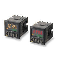
DIN 48 × 48-mm Multifunction Digital Timer/2-stage Digital Timer
* Information in this page is a reference that you created on the basis of information in the product catalog before the end of production, may be different from the current situation, such as goods for / supported standards options / price / features of the product. Before using, please check the compatibility and safety system.
Related Contents

last update: November 12, 2012
(Unit: mm)
H5CX-A[]-N/-L[]-N Digital Timers
Digital Timers
H5CX-A-N/-AS-N (Flush Mounting Models)
Note: M3.5 terminal screw (effective length: 6 mm)
H5CX-AD-N/-ASD-N (Flush Mounting Models)
Note: M3.5 terminal screw (effective length: 6 mm)
H5CX-A11[]-N (Flush Mounting/Surface Mounting Models)
H5CX-L8[]-N (Flush Mounting/Surface Mounting Models)
Dimensions with Flush Mounting Adapter
H5CX-A-N/-AS-N (Provided with Adapter and Waterproof Packing)
H5CX-AD-N/-ASD-N (Provided with Adapter and Waterproof Packing)
H5CX-A11[]-N (Adapter and Waterproof Packing Ordered Separately)
H5CX-L8[]-N (Adapter and Waterproof Packing Ordered Separately)
Panel Cutouts
Panel cutouts areas shown below. (according to DIN43700).
Note: 1. The mounting panel thickness should be 1 to 5 mm.
2. To allow easier operation, it is recommended that Adapters be mounted so that the gap between sides with
hooks is at least 15 mm (i.e., with the panel cutouts separated by at least 60 mm).
3. It is possible to horizontally mount Timers side by side.
Attach the Flush Mounting Adapters so that the surfaces without hooks are on the sides of the Timers.
(However, if Timers are mounted side by side, water resistance will be lost.)
Dimensions with Front Connecting Socket
* These dimensions vary with the type of DIN track (reference value).
Digital Timer H5CX-B[]-N
Digital Timers
Digital Timers
H5CX-BWSD-N (Flush Mounting Models)
Note: M3.5 terminal screw (effective length: 6 mm)
Dimensions with Flush Mounting Adapter
H5CX-BWSD-N (Provided with Adapter and Waterproof Packing)
Panel Cutouts
Panel cutouts areas shown below. (according to DIN43700)
Note: 1. The mounting panel thickness should be 1 to 5 mm.
2. To allow easier operation, it is recommended that Adapters be mounted so that the gap between sides with
hooks is at least 15 mm (i.e., with the panel cutouts separated by at least 60 mm).
3. It is possible to mount Timers side by side, but only in the direction without the hooks. However, if Timers are
mounted side by side, water resistance will be lost.
last update: November 12, 2012
 Product Category
- Control Components
-
Timers
-
Discontinued
- H5CX
-
Discontinued
-