Discontinued On Mar. 2022
H7CN
Solid-state Counter
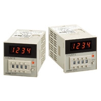
All Required Counter Functions Incorporated in a Compact DIN-sized (48 × 48) Housing
* Information in this page is a reference that you created on the basis of information in the product catalog before the end of production, may be different from the current situation, such as goods for / supported standards options / price / features of the product. Before using, please check the compatibility and safety system.
Related Contents
- Features
- Lineup
- Specifications
- Dimensions
- Catalog / Manual / CAD / Software
last update: April 3, 2017
Ratings
| Supply voltage | 24, 100 to 240 VAC 50/60 Hz
12 to 48 VDC (contains 20% ripple max.) *1 |
|---|---|
| Operating voltage range | 85% to 110% of rated voltage |
| Power consumption *2 | Approx. 12 VA/2.5 W (at 240 VAC, 50Hz)
Approx. 2.5 W (at 48 VDC) |
| Count and reset input | Impedance by short-circuiting contacts: 1 kΩ max.
Residual voltage: 2 V max. Impedance by opening contacts: 100 kΩ min. |
| Max. counting speeds of count input | 30 cps (contact and transistor inputs)
Minimum pulse width: 16.7 ms (ON/OFF ratio: 1:1) 5.000 cps (transistor inputs) Minimum pulse width: 0.1 ms (ON/OFF ratio: 1:1) |
| Reset system | Power-OFF reset
Reset time: 0.5 s Reset time following power application 0.05 s External reset & manual reset Reset time: 0.02 s Reset time following signal application: 0.05 s |
| Control output | Contact (SPDT) output: 3 A, 250 VAC, cosϕ = 1 (resistive load)
Transistor (open collector) output: 30 VDC MAX. 100 mA max. |
| Case color | Light gray (Munsell 5Y7/1) |
*1. The memory backup function is not available for this DC supply voltage range.
*2. On power application, an inrush current of approximately 10 times the normal current flows through the Counter.
Characteristics
| Item | Preset Counter | Totalizing Counter |
|---|---|---|
| Insulation resistance | 100 MΩ min. (at 500 VDC) (between current- carrying terminal and exposed non-current- carrying metal parts, and between non- continuous contacts) | 100 MΩ min. (at 500 VDC) (between current- carrying terminal and exposed non-current- carrying metal parts) |
| Dielectric strength | 2,000 VAC, 50/60 Hz for 1 min (between current-carrying terminal and exposed non- current carrying metal parts and between non-continuous contacts) | 2,000 VAC, 50/60 Hz for 1 min (between current-carrying terminal and exposed non- current carrying metal parts) |
| Impulse withstand voltage | 6 kV (between power terminals) 6 kV (between current-carrying terminal and exposed non-current-carrying metal parts) | |
| Noise immunity | ±2 kV (between power terminals), ±500 V (between input terminals), square-wave noise by noise simulator | |
| Static immunity | Malfunction: 8 kV | |
| Vibration resistance | Destruction: 10 to 55 Hz, 0.75-mm single amplitude Malfunction: 10 to 55 Hz, 0.5-mm single amplitude | |
| Shock resistance | Destruction: 300 m/s2 (approx. 30G) Malfunction: 100 m/s2 (approx. 10G) | |
| Ambient temperature | Operating: -10°C to 55°C (with no icing) Storage: -25°C to 65°C (with no icing) | |
| Ambient humidity | 35% to 85% | |
| Life expectancy | Mechanical: 10 million operations min. Electrical: 100,000 operations min. (3 A at 250 VAC, resistive load) | --- |
| Weight | Approx. 110 g | |
Applicable Standards
| Approved safety standards | UL508/CSA C22.2 No. 14
EN 61010-1 (IEC 61010-1): Pollution degree 2/overvoltage category II |
|---|---|
| EMC | (EMI) EN61326
Emission Enclosure: EN 55011 Group 1 class A Emission AC mains: EN 55011 Group 1 class A (EMS) EN61326 Immunity ESD: EN 61000-4-2 Immunity RF-interference: EN 61000-4-3 Immunity Conducted Disturbance: EN 61000-4-6 Immunity Burst: EN 61000-4-4 Immunity Surge: EN 61000-4-5 Immunity Voltage Dip/Interruption: EN 61000-4-11 |
last update: April 3, 2017
 Product Category
- Control Components
-
Counters
-
Discontinued
- H7CN
-
Discontinued
-