Discontinued On Jul. 2023
H7GP
Total Counter/Time Counter (DIN 48 x 24)
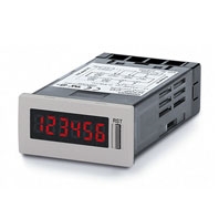
DIN 48 x 24-mm Total Counter/Time Counter with Easy-to-read Displays and Water and Oil Resistance Equivalent to IP66
* Information in this page is a reference that you created on the basis of information in the product catalog before the end of production, may be different from the current situation, such as goods for / supported standards options / price / features of the product. Before using, please check the compatibility and safety system.
Related Contents
- Features
- Lineup
- Specifications
- Dimensions
- Catalog / Manual / CAD / Software
last update: August 1, 2016
Ratings
| Item | 6-digit total counter | 6-digit time counter | |||
|---|---|---|---|---|---|
| H7GP-C | H7GP-CD | H7GP-T | H7GP-TD | ||
| Rated supply voltage | 100 to 240 VAC
(50/60 Hz) |
12 to 24 VDC *1 | 100 to 240 VAC
(50/60 Hz) |
12 to 24 VDC *1 | |
| External power supply | 50 mA at 12 VDC | --- | 50 mA at 12 VDC | --- | |
| Operating voltage range | 85% to 110% of rated supply voltage | ||||
| Power consumption | 100 to 240 VAC: 6.5 VA max.
12 to 24 VDC: 0.6 W max. |
||||
| Dimensions | 48 x 24 x 80 mm (W x H x D) | ||||
| Mounting method | Flush mounting | ||||
| External connections | Screw terminals | ||||
| Degree of protection | Panel surface: IP66 with oil resistance and NEMA Type 4 (indoors). | ||||
| Display | 7-segment, negative transmissive LCD (with red backlight) | ||||
| Digits | 6 digits (8.5-mm-high characters) | ||||
| Input mode | Up (increment) | Accumulative | |||
| Max. counting speeds | 30 Hz or 5 kHz (selected via DIP switch) | --- | |||
| Counting range | 0 to 999999 | --- | |||
| Time specification | --- | 0.1 to 99999.9 h/1 s to 99 h 59 min 59 s
(selected via DIP switch) |
|||
| Timing accuracy | --- | ±100 ppm (-10°C to 55°C) | |||
| Memory backup | EEP-ROM (overwrites: 200,000 times min.) that can store data for 20 years min. | ||||
| Input | Input signals | Count, reset, and key protection *2 | Start, reset, and key protection *2 | ||
| Input method | No-voltage input (NPN transistor input) or voltage input (PNP transistor input) (selected
via DIP switch) |
||||
| Count, reset,
start |
No-voltage input (NPN transistor input)
Short-circuit (ON) impedance: 1 kΩ max. Short-circuit (ON) residual voltage:2 VDC max. Open (OFF) impedance: 100 kΩ min. Voltage input (PNP transistor input) Short-circuit (ON) impedance: 1 kΩ max. ON voltage: 9 to 24 VDC OFF voltage: 5 VDC max. Open (OFF) impedance: 100 kΩ min. |
||||
| Key protection | No-voltage input (NPN transistor input)
Short-circuit (ON) impedance: 1 kΩ max. Short-circuit (ON) residual voltage:0.5 VDC max. Open (OFF) impedance: 100 kΩ min. |
||||
| Input
response speed |
Reset | 20 or 1 ms (automatically switched
according to counting speed) |
20 ms | ||
| Start | --- | 20 ms | |||
| Key protection | Approx. 1 s | Approx. 1 s | |||
| Reset system | External and manual resets | ||||
*1. Contains 20% ripple (p-p) max.
*2. Only a non-voltage input (NPN transistor) is possible for the key protection input. The key protection input will be a
non-voltage input even if the NPN/PNP input mode is set to PNP. Key protection is used to prohibit operating the
Reset Key. The reset input terminals will still be functional.
*2. Only a non-voltage input (NPN transistor) is possible for the key protection input. The key protection input will be a
non-voltage input even if the NPN/PNP input mode is set to PNP. Key protection is used to prohibit operating the
Reset Key. The reset input terminals will still be functional.
Characteristics
| Insulation resistance | 100 MΩ min. (at 500 VDC) |
|---|---|
| Dielectric strength | 2,000 VAC, 50/60 Hz for 1 min between current-carrying terminal and exposed non-current-
carrying metal parts (AC model) 1,000 VAC, 50/60 Hz for 1 min between current-carrying terminal and exposed non-current- carrying metal parts (DC model) 2,000 VAC, 50/60 Hz for 1 min between power terminals and control input terminals (AC model) |
| Impulse withstand
voltage |
3 kV (between power terminals) (1 kV for 12-to-24-VDC models)
4.5 kV (between current-carrying terminal and exposed non-current-carrying metal parts) (1.5 kV for 12-to-24-VDC models) |
| Noise immunity | ±1.5 kV (between AC power terminals), ±480 V (between DC power terminals),
±480 V (between input terminals); square-wave noise by noise simulator (pulse width: 100 ns/1 μs, 1-ns rise) |
| Static immunity | Display: Malfunction: 8 kV, Destruction: 15 kV
DIP switch: Malfunction: 4 kV, Destruction: 8 kV |
| Vibration resistance | Destruction: 10 to 55 Hz with 0.75-mm single amplitude, 2 hours each in three directions
Malfunction: 10 to 55 Hz with 0.5-mm single amplitude, 10 minutes each in three directions |
| Shock resistance | Destruction: 294 m/s2 each in three directions
Malfunction: 196 m/s2 each in three directions |
| Ambient temperature | Operating: -10°C to 55°C (with no icing)
Storage: -25°C to 65°C (with no icing) |
| Ambient humidity | Operating: 35% to 85% |
| EMC | (EMI) EN61326-1 (note 1.)
Emission Enclosure: EN55011 Group 1 class A Emission AC Mains: EN55011 Group 1 class A (EMS) EN61326-1 (note 1.) Immunity ESD: EN61000-4-2: 4 kV contact discharge (level 2); 8 kV air discharge (level 3) Immunity RF-interference: EN61000-4-3: 10 V/m (Amplitude-modulated, 80 MHz to 1 GHz) (level 3); 10 V/m (Pulse-modulated, 900 MHz ±5 MHz) (level 3) Immunity Conducted Disturbance: EN61000-4-6: 10 V (0.15 to 80 MHz) (according to EN61000-6-2) Immunity Burst: EN61000-4-4: 2 kV power-line (level 3); 2 kV I/O signal-line (level 4) Immunity Surge: EN61000-4-5: 1 kV line to lines (power and output lines) (level 2); 2 kV line to ground (power and output lines) (level 3) Immunity Voltage Dip/Interruption: EN61000-4-11: 0.5 cycle, 100% (rated voltage) |
| Approved standards | UL508 (note 2), CSA C22.2 No.14 (note 2), conforms to EN61010-1, VDE0106/P100 |
| Case color | Rear section: Gray smoke; Front section: 5Y7/1 (light gray) or N1.5 (black) |
| Weight | Approx. 75 g |
Note: 1. Industrial electromagnetic environment (EN/IEC 61326-1 Table 2)
2. UL508 and CAN/CSA-C22.2 No.14 certification conditions
• Power supply 100 to 240VAC types
Ambient temperature 30°C Single mounting
• Power supply 12 to 24VDC types
Ambient temperature 40°C Single mounting
last update: August 1, 2016
 Product Category
- Control Components
-
Counters
-
Discontinued
- H7GP
-
Discontinued
-