Discontinued On Mar. 2017
G2A-434
Power Relay
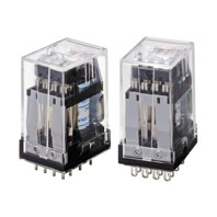
Fully Sealed Version of G2A that Displays Its Power in Adverse Environments
* Information in this page is a reference that you created on the basis of information in the product catalog before the end of production, may be different from the current situation, such as goods for / supported standards options / price / features of the product. Before using, please check the compatibility and safety system.
Related Contents
- Features
- Lineup
- Specifications
- Dimensions
- Catalog / Manual / CAD / Software
last update: September 24, 2012
Coil Ratings
| Rated voltage | Current | Coil
resistance |
Coil inductance
(ref. value) |
Must
operate |
Must
release |
Max.
voltage |
Power
con- sumption |
||
|---|---|---|---|---|---|---|---|---|---|
| 50 Hz | 60 Hz | Armature
OFF |
Armature
ON |
% of rated voltage | |||||
| 6 VAC | 295 mA | 233 mA | 8.9 Ω | 0.048 H | 0.065 H | 80 %
max. |
30 %
min. |
110% | Approx.
1.4 VA |
| 24 VAC | 73 mA | 58 mA | 136 Ω | 0.691 H | 1.04 H | ||||
| 100/110 VAC | 17.7/
21.4 mA |
14/
16.8 mA |
2,200 Ω | 12.42/
12.38 H |
18/
16.4 H |
||||
| 200/220 VAC | 8.9/
10.8 mA |
7/
8.4 mA |
8,800 Ω | 42.2/
41.8 H |
72/
65.5 H |
||||
| 12 VDC | 88 mA | 136 Ω | 0.6 H | 1.0 H | 10 %
min. |
Approx.
1.1 W |
|||
| 24 VDC | 45 mA | 530 Ω | 2.7 H | 4.6 H | |||||
| 48 VDC | 22 mA | 2,200 Ω | 11 H | 19 H | |||||
| 100 VDC | 11.4 mA | 8,800 Ω | 43 H | 73 H | |||||
Note: 1. The rated current and coil resistance are measured at a coil temperature of 23°C with tolerances of +15%/–20%
for AC rated current and ±15% for DC coil resistance.
2. The AC coil resistance and coil inductance values are for reference only.
3. Performance characteristic data is measured at a coil temperature of 23°C.
4. The maximum voltage is one that is applicable instantaneously to the Relay coil at 23°C and not continuously.
5. For built-in operation indicator models rated at 6, 12, and 24 VDC, add an LED current of approx. 5 mA to the
rated currents.
Contact Ratings
| Load | Resistive load (cosΦ = 1) | Inductive load (cosΦ = 0.4) (L/R = 7 ms) |
|---|---|---|
| Contact mechanism | Crossbar bifurcated | |
| Contact material | Movable:AgAu-clad AgPd Fixed:AgPd |
|
| Rated load | 0.3 A at 110 VAC 0.5 A at 24 VDC |
0.2 A at 110 VAC 0.3 A at 24 VDC |
| Rated carry current | 2 A | |
| Max. switching voltage | 250 VAC, 125 VDC | |
| Max. switching current | AC: 0.7 A DC: 2 A |
AC: 0.5 A DC: 1 A |
Characteristics
| Contact resistance (see note 2) | 100 mΩ max. |
|---|---|
| Operate time (see note 3) | 15 ms max. |
| Release time (see note 3) | 15 ms max. |
| Max. operating frequency | Mechanical: 18,000 operations/hour Electrical: 1,800 operations/hour (under rated load) |
| Insulation resistance (see note 4) | 100 MΩ min. (at 500 VDC) |
| Dielectric strength | 1,500 VAC, 50/60 Hz for 1 minute between coil and contact and between contacts of different polarities (700 VAC between contacts of same polarities) |
| Vibration resistance | Destruction: 10 to 55 to 10 Hz, 0.75 mm single amplitude (1.5 mm double amplitude) Malfunction: 10 to 55 to 10 Hz, 0.5 mm single amplitude (1.0 mm double amplitude) |
| Shock resistance | Destruction: 1,000 m/s2 Malfunction: 100 m/s2 |
|
Error rate (level P) (Reference value) (see note 5) |
1 mA at 100 mVDC |
| Endurance | Mechanical: 100,000,000 operations min. (at operating frequency of 18,000 operations/hour) Electrical: 5,000,000 operations min. (under rated load and at operating frequency of 1,800 operations/hour) (see note 6) |
| Ambient temperature | Operating:-10°C to 40°C (with no icing or condensation) |
| Ambient humidity | Operating:5% to 85% |
| Weight | Approx. 39 g |
Note: 1. The data shown above are initial values.
2. The contact resistance was measured with 0.1 A at 5 VDC using the voltage drop method.
3. The operate and release times were measured with the rated voltage imposed with any contact bounce ignored
at an ambient temperature of 23°C.
4. The insulation resistance was measured with a 500-VDC megger applied to the same places as those used for
checking the dielectric strength.
5. This value was measured at a switching frequency of 60 operations per minute.
6. The electrical endurance was measured at an ambient temperature of 23°C.
last update: September 24, 2012
 Product Category
- Relays
-
General Purpose Relays
-
Discontinued
- G2A-434
-
Discontinued
-