G9B
Stepping Relay Unit
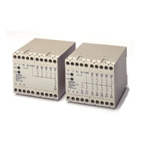
Ideal for Controlling Pumps and Production Lines with Six or Twelve Stepping Circuits
Related Contents
- Features
- Lineup
- Specifications
- Dimensions
- Catalog / Manual / CAD / Software
last update: September 24, 2012
Contact Ratings
| Load | Resistive load (cosΦ = 1) |
|---|---|
| Rated load | 2 A at 250 VAC/30 VDC |
| Rated carry current | 2 A |
| Max. switching voltage | 250 VAC, 30 VDC |
| Max. switching current | 2 A |
Characteristics
| Operating voltage range | 85% to 110% of rated voltage |
|---|---|
| Power consumption | 24 VDC: 90 mA max. 100 or 200 VAC: 120 mA max. |
|
Contact resistance (See note 2.) |
100 mΩ max. |
| Operate time (See note 3.) | 50 ms max. |
| Release time (See note 3.) | 50 ms max. |
| Min. pulse time (See note 4.) | 100 ms max. |
| Error detecting time | 100 ms max. |
|
Insulation resistance (at 500 VDC) |
100 MΩ min. between the power supply, control, output, and R terminals 100 MΩ min. between the terminals, except the alarm output terminals and power output terminals |
| Dielectric strength | 1,500 V, 50/60 Hz for 1 min between the power supply, control, output, and R and other terminals 1,500 V, 50/60 Hz for 1 min between the terminals, except the alarm output terminals and power output terminals |
| Noise immunity | Noise level: 1.5 kV, pulse width: 50 ns/1 μs (600 V for 24-VDC model) |
| Vibration resistance | Destruction: 10 to 55 to 10 Hz, 0.75-mm single amplitude (1.5 mm double amplitude) Malfunction: 10 to 55 to 10 Hz, 0.75-mm single amplitude (1.5 mm double amplitude) |
| Shock resistance | Destruction: 500 m/s2 Malfunction: 200 m/s2 |
| Endurance | Mechanical: 10,000,000 steps min. Electrical: 300,000 steps min. (See note 5.) |
| Error rate (See note 6.) | 10 mA at 5 VDC |
| Ambient temperature | Operating: -25°C to 55°C (with no icing or condensation) |
| Ambient humidity | Operating: 5% to 85% |
| Terminal strength | Tightening torque: 0.98 Nm Tensile strength: 49 N |
| Weight | Twelve-step model: approx. 450 g; Six-step model: approx. 400 g |
Note: 1. The data shown above are initial values.
2. The contact resistance was measured with 0.1 A at 5 VDC using the fall-of-potential method.
3. The operate time and release time was measured with the rated voltage imposed with any contact bounce
ignored at an ambient temperature of 23°C.
4. For the step signal, set a minimum pulse time of 100 ms for both the ON time and OFF time.
5. The electrical endurance was measured at an ambient temperature of 23°C.
6. This value was measured at a switching frequency of 120 operations per minute.
last update: September 24, 2012