CJ1W-SCU
CJ-series Serial Communications Units
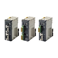
The Serial Communications Units That Enable High-speed Connections with External Devices. This unit is available for CJ/NJ controller.
Related Contents
- Features
- Lineup
- Specifications
- Dimensions
- Catalog / Manual / CAD / Software
last update: April 1, 2021
| Item | Description | ||||||
|---|---|---|---|---|---|---|---|
| Device name | Serial Communications Unit | ||||||
| Classification | CPU Bus Unit | ||||||
| Model number | CJ1W-SCU22 | CJ1W-SCU32 | CJ1W-SCU42 | CJ1W-SCU21-V1 | CJ1W-SCU31-V1 | CJ1W-SCU41-V1 | |
| Serial
ports |
Port 1 | RS-232C | RS-422A/485 | RS-422A/485 | RS-232C | RS-422A/485 | RS-422A/485 |
| Port 2 | RS-232C | RS-422A/485 | RS-232C | RS-232C | RS-422A/485 | RS-232C | |
| Protocol | Port 1 | Host Link, protocol macro, Serial Gateway, No-
protocol, NT Link, Modbus-RTU Slave, loopback test , or 1:1 Host Link can be selected for each port. *1, *2 |
Host Link, protocol macro, NT Link, or loopback test can be
selected for each port. Unit Ver. 1.2 or later also supports Serial Gateway, no- protocol, and 1:1 Host Link modes. (Note: The Serial Gateway can also be executed in protocol macro mode.) *1 Unit Ver. 1.3 or later also supports Modbus-RTU slave mode. |
||||
| Port 2 | |||||||
| Number
of mountable Units |
CPU Unit | None | |||||
| CPU Rack | A total of up to 16 Units, including all other
CPU Bus Units. No restrictions on the mounting location. However, if an external interrupt task is used, the Unit must be mounted in one of the following slots on the CPU Rack. CJ2H-CPU6[]-EIP CPU Unit: Slots 0 to 3 CJ2H-CPU6[], CJ2M-CPU[][] or CJ1G/H- CPU[][]H CPU Unit: Slots 0 to 4 CJ1M-CPU[][] CPU Unit*4: Slots 0 to 2 External interrupt tasks will not be started if the Unit is mounted to any other slot. |
A total of up to 16 Units, including all other CPU Bus Units.
No restrictions on the mounting location. |
|||||
| Expansion
Rack |
|||||||
| Data
exchange with the CPU Unit |
Ordinary
refreshing of software switches and status |
Allocated 25 words of the 25 words in the CPU Bus Unit CIO Area (constant data exchange with the CPU Unit) | |||||
| Transfer
from the CPU Unit set by the system |
Of the CPU Bus Unit DM Area, each serial port is allocated 10 words (total 20 words).
Data is transferred from the CPU Unit at the following times: Startup or restart Ladder instruction: STUP (237) Port Settings Changing Flag turns ON (Auxiliary Area) |
||||||
| Simple Backup Function | The CPU Unit's Simple Backup Function can be used to backup the Protocol Macro data in the Serial
Communications Unit to the CPU Unit's Memory Card. The backed-up data can be restored or compared. (The Simple Backup Function can be used with the CJ1-H and CJ1M CPU Units only.) |
||||||
| Current consumption
*3 |
280mA+x | 400mA | 360mA+x | 280mA+x | 380mA | 380mA+x | |
| Weight | 160g Max. | 120g Max. | 140g Max. | 110g Max. | 110g Max. | 110g Max. | |
| General specifications | Conforms to general specifications for CJ Serise. | ||||||
*1. Serial Gateway: The Serial Gateway can also be executed in protocol macro mode.
*2. No-protocol: An external interrupt task can be executed when data is received in No-protocol Mode. If the CJ2H CPU
Units with unit version 1.1 or later and CJ2M CPU Units is used, the high-speed communications instructions
(DRXDU(261) and DTXDU(262)) can also be used.
*3. The current consumption is for one Serial Communications Unit. When an NT-AL001 Link Adapter is connected to the
Serial Communications Unit, power is supplied to the Link Adapter from the Unit. A current consumption of 0.15A
must be added for each Link Adapter that is connected. In the above specifications, “x” indicates that 0.15A must be
added for each port to which an NT-AL001 Link Adapter is connected to provide the required 5-V power supply.
*4. Final order entry date for CJ1M:The end of March, 2021
Protocol Specifications
Host Link Specifications
| Item | Description | ||
|---|---|---|---|
| Communications mode | Half-duplex (Full-duplex for slave-initiated communications) | ||
| Synchronous mode | Start-stop synchronization (asynchronous mode) | ||
| Baud rate *1 | RS-232C port and RS-422A/485 ports: 1,200/2,400/4,800/9,600/19,200/38,400/57,600/115,200/230,400 bps *2 Default setting: 9,600 bps |
||
| Communications distance *1 | RS-232C port: 15 m max. *3 RS-422A/485 Port: CJ1W-SCU[]1-V1 500 m max. (total cable length: 500 m max., T-branch branch lines: 10 m max.) CJ1W-SCU[]2 1,200 m max. (total cable length: 1,200 m max., Multidrop connections are possible. However, maximum cable length is 500 m if the NT-AL001 is used for RS-422A-485 connections.) |
||
| Connection configuration | RS-232C port: 1:1 (1:N (N = 32 Units max.) is possible using an Converting Link Adapters.) RS-422A/485 port: 1:N (N = 32 Units max.) |
||
| Number of connected Units | 32 Units max. (unit numbers 0 to 31; unit number 0 is set for 1:1 connection) | ||
| Frame structure | C-mode commands | Header: @, address: (host link unit number) 0 to 31 (BCD), data: header code + text, error check code: FCS, terminator: * +CR |
|
| FINS commands | Header: @, address: (host link unit number) 0 to 31 (BCD), data: header code (always "FA") + FINS header + FINS command + text, error check code: FCS, terminator: * +CR |
||
| Error check codes | Vertical parity: Even, odd. or none FCS (horizontal parity converted to ASCII) |
||
| Command flow and support | Command flow | Commands | Contents |
| Host computer to Controller |
C-mode commands | 1:1 or 1:N communications with directly connected Controller *4 |
|
| FINS commands (in Host Link protocol) |
1:1 or 1:N communications with directly connected Controller. |
||
| Controller to host computer |
FINS commands (in Host Link protocol) |
Communications using SEND(090), RECV(098), and CMND(490) from CPU Unit. *5 |
|
*1. Confirm the baud rates and communications distance supported by connected devices.
*2. The CJ1W-SCU[]2 is required for communications at 230,400 bps.
*3. The maximum cable length for RS-232C is 15 m. The RS-232C standard, however, does not cover baud rates above
19.2 Kbps. Refer to the manual for the device being connected to confirm support.
*4. The specified frame format must be prepared on the host computer and then sent.
*5. The host computer must interpret the commands and return a response in the correct format.
Connection between the host computer and Controller must be 1:1.
Protocol Macro Function Specifications
| Item | Description | ||||||
|---|---|---|---|---|---|---|---|
|
Number of protocols |
20 max. | Can be created and registered with the Protocol Support Tool (CX-Protocol). | |||||
|
Number of sequences |
1,000 max. | ||||||
| Per protocol | Number of sequences | 60 max. | |||||
| Number of messages | 300 max. | ||||||
|
Number of reception matrixes |
100 max. | ||||||
| Sequence execution condition | Using the CPU Unit's PMCR (260) instruction (specifying the sequence number) | ||||||
| Communications mode | Half-duplex or full-duplex | ||||||
| Synchronous mode | Start-stop synchronization (asynchronous mode) | ||||||
| Baud rate *1 | RS-232C port and RS-422A/485 ports: 1,200/2,400/4,800/9,600/19,200/38,400/57,600/115,200/230,400 bps Default setting: 9,600 bps *2 |
||||||
| Communications distance *1 | RS-232C port: 15 m max. RS-422A/485 port: CJ1W-SCU[]1-V1 500 m max. (total cable length: 500 m max., T-branch branch lines: 10 m max.) CJ1W-SCU[]2 1,200 m max. (total cable length: 1,200 m max., Multidrop connections are possible. However, maximum cable length is 500 m if the NT-AL001 is used for RS-422A-485 connections.) |
||||||
| Connection configuration | RS-232C port: 1:1 (1:N (N = 32 Units max.) is possible using a Converting Link Adapter.) RS-422A/485 port: 1:N (N = 32 Units max.) |
||||||
| Number of connected Units | 32 Units max. (unit numbers 0 to 31; unit number 0 is set for 1:1 connection) | ||||||
|
Maximum number of data exchange words between Controller and protocol macro function |
Operand setting | 250 words | Including the word that specifies the number of words (1 word) |
||||
| Link word setting | 500 words | O1, O2, I1, and I2: 500 words total | |||||
| Direct setting | 500 words | Maximum number of words per data attribute | |||||
|
Sequence contents (step common parameters) |
Number of steps per sequence |
16 max. | |||||
|
Transmission control parameters |
X-on/X-off flow, RS/CS flow, delimiter control, or contention control, and modem control can be selected. |
||||||
|
Response notification method (operand) |
Scan notification: Writes the receive data to I/O memory during CPU Unit scanning. | ||||||
| Scan method (fixed) | Support | ||||||
| Interrupt notification | Not support | ||||||
| Interrupt notification for reception case number | Not suppprt | ||||||
|
Monitoring time during send/receive processing |
Receive wait, receive completion, or send completion can be monitored. Setting range: 0.01 to 0.99 s, 0.1 to 9.9 s, 1 to 99 s, or 1 to 99 minutes |
||||||
| Link word setting | Area in which data is exchanged between the CPU Unit and the Serial Communications Unit during Communications Unit refreshing. Two areas are possible for each device: An area for storing receive data and an area for storing send data. *3 |
||||||
|
Step contents |
Commands | Send only (SEND), receive only (RECV), send and receive (SEND&RECV), wait (WAIT), reception buffer clear (FLUSH), ER-ON (OPEN), or ER-OFF (CLOSE) |
|||||
| Repeat counter | 1 to 255 times | ||||||
| Retry count | 0 to 9 (Only when the command is SEND&RECV) | ||||||
| Send wait time | 0.01 to 0.99 s, 0.1 to 9.9 s, 1 to 99 s, or 1 to 99 minutes (Only when the command is SEND or SEND&RECV) |
||||||
|
With or without response write (operand) |
When receive processing is completed (when the receive data is stored in the area specified in the 4th operand of the PMCR(260) instruction), whether or not to store the received messages can be selected. |
||||||
| Next processing | When a step has ended normally, End (sequence completed), Next (proceed to the next step No.), Goto (go to the specified step No.), or Abort (interrupt the step and terminate that sequence) can be selected. |
||||||
| Error processing | When a step has ended abnormally, End, Next, Goto, or Abort can be selected. | ||||||
| Send message | Data sent to the specified address when the command is SEND or SEND&RECV. |
Consists of a header, address, length, data, error check code, and terminator. |
|||||
| Receive message | Data sent from the specified address when the command is RECV or SEND&RECV. |
||||||
| Reception matrix | When the command is RECV or SEND&RECV, sets the expected receive messages (15 max.), and switches to the next processing according to the message received. |
Specifies the receive messages and the next processing for each of cases No. 00 to No. 15. Of the maximum 16 cases, one case must be set as "Other" in the receive messages (in addition to the set receive messages). |
|||||
|
Message unit contents |
Header and terminator data attributes |
Constant | ASCII data, hexadecimal data, or control code | ||||
|
Data attributes of addresses and data in send/ receive messages |
Constant | ASCII data, hexadecimal data, or control code (with an address, no control code is possible) | |||||
| Variable | No conversion, conversion to ASCII data, or conversion to hexadecimal data (the read/write direction can be specified) |
||||||
| Designation method |
(X, Y) X: Effective address (where read from, or where written to) Y: Data size (1 to 1,000) *4 |
||||||
| X | Word designation |
Word read (I/O memory to send data) |
Specify using the 3rd operand of the PMCR(260) instruction. |
Set leading address + n (The linear expression aN + b, including repeat counter N, is also possible for n.) |
|||
| Specify using a link word. |
|||||||
| I/O memory direct designation |
|||||||
| Word write (receive data to I/O memory) |
Specify using the 4th operand of the PMCR(260) instruction. |
||||||
| Specify using a link word. |
|||||||
| I/O memory direct designation |
|||||||
| Wild card | * | Any data or address can be received (only in receive messages) |
|||||
| Repeat counter | N | ||||||
| Y | Linear expression including repeat counter |
aN+b | a: 0 to 1000; b: 1 to 1000 N: Repeat counter value |
||||
| Wild card | * | Can be received regardless of the length (only in receive messages) |
|||||
| Word designation | Word read (I/O memory to send data) |
Specify using the 3rd operand of the PMCR(260) instruction. |
Set leading address + n (The linear expression aN + b, including repeat counter N, is also possible for n.) |
||||
| Specify using a link word. |
|||||||
| I/O memory direct designation |
|||||||
| Error check codes | LRC, LRC2, CRC-CCITT, CRC-16, SUM, SUM1, and SUM2 can be calculated. | ||||||
|
Maximum length of send/receive messages |
1,000 bytes. (A maximum length between 200 and 1,000 bytes can be set in the Setup Area.) | ||||||
|
Maximum number of data attributes registered in one message |
96 attributes *5 | ||||||
|
Maximum number of write data attributes registered in one message |
30 attributes *6 | ||||||
| Trace function *7 | A total of up to 1,700 bytes (characters) of time-series data can be traced in send and receive messages. Changes to the step No. and control signals such as RS and CS can also be traced. |
||||||
*1. The baud rate and the communications distance sometimes depend on the remote device.
*2. A baud rate of 57,600 bps can be selected when using Unit Ver. 1.2 or later (115,200 bps is not possible). The CJ1W-
SCU[]2 is required for communications at 115,200 or 230,400 bps.
*3. Unit Ver. 1.2 or later supports continuous I/O refreshing in addition to the previous on-request I/O refreshing.
*4. The data size is the number of bytes on the transmission path.
*5. The CX-Protocol can be used to register up to 96 attributes per message.
*6. A macro syntax error will occur when the protocol macro is executed if more than 31 write attributes are registered in
one message.
*7. The CPU Unit is set to the RUN/MONITOR mode. (MONITOR mode is not available with the NJ-series CPU Units.)
Note: When using 2-wire RS-422A/485 communications in Protocol Macro Mode, set only modem controls for the send
control parameters, and do not use RS/CS flow controls.
Serial Gateway Specifications
| Item | Description |
|---|---|
| Conversion source | FINS commands (received through network (including Host Link FINS) or CPU bus) |
| Conversion functions | The received FINS command sent to the Unit's serial port is converted according to the FINS command code as follows: 2803 hex: FIN header removed and converted to Compo-Way/F command. 2804 hex: FIN header removed and converted to Modbus-RTU command. 2805 hex: FIN header removed and converted to Modbus-ASCII command. The converted command is sent to the serial port. When the received FINS command is sent to the Unit (user-specified FINS command code), the FINS command is enclosed in a Host Link header and terminator. |
| Converted format | CompoWay/F commands Modbus-RTU commands Modbus-ASCII commands Host Link FINS commands |
|
Enabled serial communications mode |
Serial Gateway mode or protocol macro mode |
| Queuing functions | Up to five FINS commands can be converted and then queued for processing. |
|
Protocol macro execution processing |
When a FINS command is received during protocol macro execution, the Serial Gateway is executed using an interrupt between steps in the communications sequence. If the next step is a RECEIVE command, the Serial Gateway will not be executed until the next step. For other conditions, the interrupt is executed immediately. *1 |
|
Response timeout monitoring |
The time is monitored from when the message is converted into the specified protocol using the Serial Gateway until the response is received (in Serial Gateway mode or protocol macro mode). Default: 5 s (setting range: 0.1 to 25.5 s) *2 |
|
Send start timeout monitoring |
The time is monitored from when the FINS command is received until it is converted into the specified protocol and starts to be sent (in protocol macro mode only). Default: 5 s (setting range: 0.1 to 25.5 s) *3 |
| Send delay | The time can be set from when the message is converted into another protocol using Serial Gateway conversion until the data is actually sent. (Serial Gateway or protocol macro mode) Default: 0 s (setting range: 0.01 to 300.00 s) |
*1. The reception buffer is cleared during Serial Gateway execution.
The Serial Gateway can be prohibited in protocol macro mode by turning ON the Serial Gateway Prohibit Switch in the
CIO Area.
*2. When a timeout occurs, the FINS end code (0205 hex: Response timeout) is returned to the source of the FINS
command and a response is received after a timeout occurs.
*3. When a timeout occurs, the FINS end code (0204 hex: Remote node busy) is returned to the source of the FINS
command. The send processing will not be executed and the received FINS command will be discarded.
No-protocol Specifications
| Item | Description | |
|---|---|---|
| Communications mode | Full-duplex | |
| Baud rate *1 | RS-232C port and RS-422A/485 ports: 1,200/2,400/4,800/9,600/19,200/38,400/57,600/115,200/230,400 bps *2 Default setting: 9,600 bps |
|
|
Communications distance *1 |
RS-232C port: 15 m max. RS-422A/485 port: CJ1W-SCU[]1-V1 500 m max. (total cable length: 500 m max., T-branch branch lines: 10 m max.) CJ1W-SCU[]2 1,200 m max. (total cable length: 1,200 m max., Multidrop connections are possible. However, maximum cable length is 500 m if the NT-AL001 is used for RS-422A-485 connections.) |
|
|
Messages (communications frame structure) |
Set either of the following types in the Setup Area in the allocation DM Area. 1. Data only (without start code and end code) 2. Start code + data 3. Data + end code 4. Start code + data + end code 5. Data + CR + LF 6. Start code + data +CR + LF Set in allocated DM Area (The start code can be included by setting it to between 00 and FF hex, and the end code can be included by setting it to between 00 and FF hex. To exclude the end code, set the number of receive data bytes.) |
|
| Start code | None or 00 to FF hex | |
| End code | None, 00 to FF hex, or CR + LF | |
| Number of receive data bytes during reception |
Set the number of receive data bytes between 1 and 256 bytes (according to the DM Area settings) when frame structure 1 or 2 above is used. |
|
| Sending messages | CJ: TXDU (256) instruction *3 | |
| NJ: SerialSend instruction | ||
| Receiving messages | CJ: RXDU (255) instruction *3 | |
| NJ: SerialRcv or SerialRcvNoClear instruction *4 | ||
|
Maximum message length |
Sending and receiving: Up to 259 bytes including the start code and end code (up to 256 bytes excluding start/end codes) |
|
| Data conversion | No conversion | |
|
Communications protocol |
None | |
| Message delay time | CJ: When the TXD (236), TXDU (256) instruction is executed, after the send delay time, the data is sent from the port. *3 0 to 300 s (0 to 300,000 ms) (Can be set in 10-ms units depending on the DM Area settings) |
|
| NJ: When the SerialSend instruction is executed, after the send delay time, the data is sent from the port. 0 to 300 s (0 to 300,000 ms) (Can be set in 10-ms units: Set in System Studio or by using a device variable for CJ-series Unit.) |
||
| Receive counter | The number of data bytes (0 to 256) received at the port can be counted. | |
|
Reception buffer clear timing |
CJ1W-SCU[]1-V1 The reception buffer is cleared immediately after executing the RXD(235)/RXDU(255) instruction CJ1W-SCU[]2 With the DRXDU (261) instruction, you can specify whether the reception buffers will be cleared or not in a setting in the DM Area words allocated to the Unit. *3 NJ SerialRcv instruction: After reading the receive data SerialRcvNoClear instruction: When the receive data size variable (Size) is set to 0 *4 |
|
*1. The baud rate and the communications distance sometimes depend on the remote device.
*2. The CJ1W-SCU[]2 is required for communications at 115,200 or 230,400 bps.
*3. The DTXDU (262) and DRXDU (261) instructions can be used only when a CJ1W-SCU[]2 Serial Communications Unit
is connected to the CJ2H CPU Units with unit version 1.1 or later and CJ2M CPU Units.
*4. A Serial Communications Unit with unit version 2.1 or later, a CPU Unit with unit version 1.03 or later, and Sysmac
Studio version 1.04 or higher are required to use the SerialRcvNoClear instruction.
Modbus-RTU Specifications
| Item | Description |
|---|---|
| Mode | Modbus-RTU slave mode *1 |
| Baud rate | 1,200/2,400/4,800/9,600/19,200/38,400/57,600/115,200/230,400 bps *2 Default: 19,200 bps |
| Data length | 8 bits |
| Parity | Odd, even, or none Default: Even |
| Stop bits | Odd or even parity: 1 bit No parity: 2 bits |
| Address setting range | 1 to 247 (broadcasting: 0) |
| Frame format | Slave address: 1 byte Function code: 1 byte Data: 0 to 252 bytes CRC code: 2 bytes |
*1. Modbus-ASCII mode is not supported.
*2. The CJ1W-SCU[]2 is required for communications at 230,400 bps.
Supported Commands
|
Function code (hexadecimal) |
Function | Modbus name |
|---|---|---|
| 1 | Reads multiple bits from the CIO, Work, Holding, or Auxiliary Area of I/O memory. | Read Coils |
| 2 | Reads multiple bits from the CIO Area of I/O memory. | Read Discrete Inputs |
| 3 | Reads multiple words from the DM or EM Area of I/O memory. | Read Holding Registers |
| 4 | Reads multiple words from the CIO, Work, Holding, or Auxiliary Area of I/O memory. | Read Input Registers |
| 5 | Writes a bit in I/O memory. | Write Single Coil |
| 6 | Writes a word in the DM or EM Area of I/O memory. | Write Single Register |
| 8 | Executes an echoback test. | Diagnostic |
| 0F | Writes multiple bits in I/O memory. | Write Multiple Coils |
| 10 | Writes multiple words in the DM or EM Area of I/O memory. | Write Multiple Registers |
last update: April 1, 2021