OS32C
Safety Laser Scanner
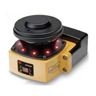
Compact (104.5 mm), lightweight (1.3 kg) and easy-to-install Safety Laser Scanner
Related Contents
- Features
- Lineup
- Specifications
- Dimensions
- Catalog / Manual / CAD / Software
last update: October 1, 2025
Rating/Performance
| Sensor Type | Type 3 Safety Laser Scanner | |
|---|---|---|
| Performance Level (PL)/
Category |
PLd/Category 3 (ISO 13849-1) | |
| Functional Safety of
Electrical/ Electronic/Programmable Electronic Safety-related Systems |
SIL 2, PFHD = 8.3 × 10⁻⁸(IEC 61508) | |
| Detection Capability | Configurable via the configuration tool; Non-transparent with a diameter of 30, 40, 50, 70mm
(1.8% reflectivity or greater) (default: 70 mm) |
|
| Monitoring Zone | Monitoring Zone Set Count: (Safety Zone + 2 Warning Zones) x 70 sets | |
| Operating
Range |
OS32C-[][][] | Safety Zone: 1.75 m (min. obj. resolution of 30 mm)
2.5 m (min. obj. resolution of 40 mm) 3.0 m (min. obj. resolution of 50 mm or 70 mm) Warning Zone: 10.0 m |
| OS32C-[][][]-4M | Safety Zone: 1.75 m (min. object resolution of 30mm)
2.5 m (min. object resolution of 40 mm) 3.0 m (min. object resolution of 50 mm) 4.0 m (min. object resolution of 70 mm) Warning Zone: 15.0 m |
|
| Maximum Measurement Error | 100 mm (at range of 3 m or less) *1
110 mm (at distance greater than 3 m and up to 4m) *1 |
|
| Detection Angle | 270° | |
| Angular Resolution | 0.4° | |
| Laser Beam Diameter | 6 mm at optics cover, 14 mm (typical) at 3 m. | |
| Laser Scan Plane Height | 67mm from the bottom of the scanner
(see "External Dimensional Drawings" on Catalog for more detail.) |
|
| Response Time | Response time from ON to OFF:
From 80 ms (2 scans) to 680 ms (up to 17 scans) *8 Response time from OFF to ON: Response time from ON to OFF + 100 ms to 60 s (Configurable) |
|
| Zone Switching Time | 20 to 320 ms | |
| Line Voltage | 24 VDC +25%/-30% (ripple p-p 2.5 V max.) *2 | |
| Power Consumption | Normal operation: 5 W max. *3
Standby mode: 3.75 W (without output load) |
|
| Emission Source (Wavelength) | Infrared Laser Diode (905 nm) | |
| Laser Class | Class 1 Laser Product: IEC 60825-1:2014, EN 60825-1:2014+A11:2021 | |
| Class 1 Laser Product: JIS C 6802: 2014 | ||
| Class I: 21 CFR 1040.10, 1040.11 | ||
| 1类激光产品: GB/T 7247.1-2024 | ||
| Safety Output (OSSD) | PNP transistor x 2, load current of 250 mA max., residual voltage of 2 V max.,
load capacity of 2.2 μF max., leak current of 1 mA max. *3, *4, *5 |
|
| Auxiliary Output (Non-Safety) | NPN/PNP transistor x 1, load current of 100 mA max.,
residual voltage of 2 V max., leak current of 1 mA max. *4, *5, *7 |
|
| Warning Output (Non-Safety) | NPN/PNP transistor x 1, load current of 100 mA max.,
residual voltage of 2 V max., leak current of 1 mA max. *4, *5, *7 |
|
| Operation Mode | Auto Start, Start Interlock, Start/Restart Interlock | |
| Input | External Device
Monitoring (EDM) |
ON: 0 V short (input current of 50 mA), OFF: Open |
| Start | ON: 0 V short (input current of 20 mA), OFF: Open | |
| Zone Select | ON: 24 V short (input current of 5 mA), OFF: Open | |
| Stand-by | ON: 24 V short (input current of 5 mA max.), OFF: Open | |
| Connection Type | Power Cable: 18-pin mini-connector (pigtail)
Communication Cable: M12, 4-pin connector |
|
| Connection with PC | Communication: Ethernet *6
OS Supported:Windows XP (32-bit version, Service Pack 3 or later), Windows 7 (32-bit version/64-bit version), Windows 8.1 (32-bit version/64-bit version), Windows 10 (32-bit version/64-bit version), Windows 11 (64-bit version) |
|
| Indicators | RUN indicator: Green, STOP indicator: Red, Interlock Indicator: Yellow,
Warning Output Indicator: Orange Status/Diagnostic Display: 2 x 7-segment LEDs, Individual Sector Indicators: Red LED x 8 |
|
| Protective Circuit | Protection against output load short and reverse power connection | |
| Ambient Temperature | Operation: -10 to 50 °C, Storage: -25 to 70 °C | |
| Ambient Humidity | Operation & Storage: 95% RH max., non-condensing | |
| Ambient Operation
Illumination |
Incandescent lamp: Illumination on receiving surface 1500 lx max.
(an angle of laser scanning plane and disturbance light must be +/-5 degrees or more) |
|
| Insulation Resistance | 20 MΩ or higher (500 VDC) | |
| Dielectric Withstand Voltage | 350VDC, 1 minute | |
| Enclosure Rating | IP65 (IEC 60529) | |
| Enclosure | Sensor head: Die-cast aluminum, optical cover: Polycarbonate, I/O block: Die-cast aluminum | |
| Dimensions (WxHxD) | 133.0 x 104.5 x 142.7 mm (except cable) | |
| Impact Resistance | 98 m/s2 1,000 times for each of X, Y, and Z directions (IEC 60068-2-29) | |
| Vibration | 10 to 55 Hz double-amplitude of 0.7 mm, 20 sweepings for X, Y, and Z directions (IEC 60068-2-6) | |
| Weight (Main Unit only) | 1.3 kg | |
| Power Cable | Up to 30 m | |
| Communication Cable | Up to 100 m for 100BASE-TX cable *9 | |
| Approvals | Certificated by: TÜV Rheinland, UL | |
| EN IEC 61496-1 (Type 3 ESPE), EN IEC 61496-3 (Type 3 AOPDDR), EN 61508 (SIL2),
IEC 61496-1 (Type 3 ESPE), IEC 61496-3 (Type 3 AOPDDR), IEC 61508 (SIL2), UL 508, UL 1998, CAN/CSA-C22.2 No. 14, CAN/CSA-C22.2 No. 0.8 |
||
*1. An additional measurement error may need to be added due to reflective backgrounds.
*2. For power source specification, refer to “Safety Precautions” on Catalog.
*3. Rated current of OS32C is 1.025 A max. (OS32C 210 mA + OSSD A load + OSSD B load + Auxiliary output load +
Warning output load + Functional Inputs).
Where functional inputs are: EDM input ... 50 mA Start input ... 20 mA Standby input ... 5 mA Zone X input ... 5 mA x 8
(eight zone set select inputs)
*4. Output voltage is Input voltage - 2.0 VDC.
*5. Total consumption current of 2 OSSDs, auxiliary output, and warning output must not exceed 700 mA.
*6. An ethernet cable with an M12, 4-pin connector is required.
*7. Output polarity (NPN/PNP) is configurable via the configuration tool.
*8. Pollution Tolerance mode will add 6 ms to each scan time.
*9. Omron only supplies up to a 15 m Ethernet cable. For longer lengths a connection to a network switch/router is needed.
last update: October 1, 2025