G2RV-SR
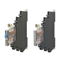
Slim I/O Relay

Our Value Design Products Increase the Value of Your Control Panels. Global standard size, low profile slim I/O relay with width 6.2 mm.
* Information in this page is a reference that you created on the basis of information in the product catalog before the end of production, may be different from the current situation, such as goods for / supported standards options / price / features of the product. Before using, please check the compatibility and safety system.
- Features
- Lineup
- Specifications
- Dimensions
- Catalog / Manual / CAD / Software
last update: January 5, 2022
Ratings
Coil ratings
| Rated input
voltage |
Rated current | Must
operate voltage |
Must
release voltage |
Power consumption | Maximum
allowable voltage |
|||
|---|---|---|---|---|---|---|---|---|
| AC | DC | Percentage of
the rated voltage |
AC (VA) | DC (mW) | Percentage
of the rated voltage |
|||
| 50 Hz | 60 Hz | |||||||
| 12 VDC | - | - | 27.9 mA | 80% max.* | 10% min. | - | Approx. 300 mW | 110% |
| 24 VDC | - | - | 13.5 mA | - | Approx. 300 mW | |||
| 24 VAC/VDC | 12.5 mA | 12.6 mA | 12.6 mA | Approx. 0.5 VA | Approx. 300 mW | |||
| 48 VAC/VDC | 5.9 mA | 6.1 mA | 5.2 mA | Approx. 0.4 VA | Approx. 250 mW | |||
| 100 VAC | 5.9 mA | 6.0 mA | - | Approx. 0.8 VA | - | |||
| 110 VAC | 5.9 mA | 5.9 mA | - | Approx. 0.8 VA | - | |||
| 200 VAC | 6.6 mA | 7.6 mA | - | Approx. 1.7 VA | - | |||
| 230 VAC | 7.3 mA | 8.4 mA | - | Approx. 1.7 VA | - | |||
* Operating voltage will be, for mounting in the upside down direction, 85% max.
(Upside down: Direction in which the mechanical indicator faces down)
Contact ratings
| Item | Standard
(G2RV-SR700, 500, 701, 501) |
For microloads
(G2RV-SR700-AP, 500-AP) *2 |
|
|---|---|---|---|
| Contact configuration | SPDT | ||
| Load | Resistive load
(cosφ=1) |
Inductive load
(cosφ=0.4, L/R=7ms) |
Resistive load
(cosφ=1) |
| Rated load | 6 A at 250 VAC
6 A at 30 VDC |
2.5 A at 250 VAC
2 A at 30 VDC |
50 mA at 30 VAC
50 mA at 36 VDC |
| Rated carry current | 6 A | 50 mA | |
| Maximum switching voltage | 440 VAC, 125 VDC | 30 VAC, 36 VDC | |
| Maximum switching current | 6 A | 50 mA | |
| Maximum switching power | 1,500 VA
180 W |
500 VA
60 W |
- |
| Failure rate P value
(reference value) *1 |
10 mA at 5 VDC | 1 mA at 100 mVDC | |
*1. P level: λ60=0.1×10⁻⁶/times
This value is the value in switching frequency 120 operations/min.
*2. If the Au plating layer is destroyed, the number will be the same as the standard type.
Characteristics
| Item | Standard
(G2RV-SR700, 500, 701, 501) |
For microloads
(G2RV-SR700-AP, 500-AP) |
|
|---|---|---|---|
| Contact resistance *1 | 100 mΩ max. | ||
| Operate (Set) time *1 | 20 ms max. | ||
| Release time *1 | AC, AC/DC: 40 ms max.
DC: 20 ms max. |
||
| Maximum operating
frequency |
Mechanical: 18,000 operations/h
Electrical: 1,800 operations/h (rated load) |
||
| Insulation resistance | 1,000 MΩ min. (at 500 VDC) | ||
| Dielectric strength | Between coil and contacts: 4,000VAC 50/60 Hz 1 min
Contact between the same polarity: 1,000 VAC 50/60 Hz 1 min |
||
| Vibration resistance *2 | Destruction: 10 to 55 to 10 Hz, single amplitude 0.50 mm (double amplitude 1.0 mm)
Malfunction: 10 to 55 to 10 Hz, single amplitude 0.50 mm (double amplitude 1.0 mm) |
||
| Shock resistance *2 | Destruction: 1,000 m/s2
Malfunction: Energized 200m/s2, Non-energized 100m/s2 |
||
| Endurance *1 | Mechanical | 5,000,000 operations min. | |
| Electrical | NO contact: 70,000 operations min.
NC contact: 50,000 operations min. |
5,000,000 operations min. | |
| Ambient operating
temperature |
Operating: -40 to +55°C (with no icing or condensation) | ||
| Ambient operating
humidity |
Operating: 5 to 85% RH | ||
| Weight | Approx. 30 g | ||
| Contact material | Ag alloy | Ag alloy + Au plating | |
Note: Above values are initial values.
*1. Value is at ambient temperature of 23°C.
*2. Value when the end plate is used.
Approved standards
UL (File No.E41643)
| Model | Contact form | Operation coil ratings | Contact ratings | Operations |
|---|---|---|---|---|
| G2RV-SR series | SPDT | 12 to 48 VDC
24 to 230 VAC |
6 A at 250 VAC (Resistive load)
6 A at 30 VDC (Resistive load) 2 A at 400 VAC (Resistive load)* |
6,000 |
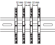
* If the load voltage exceeds 250 VAC, please attach with a spacing of 12 mm min., or use a separate plate (XW5Z-EP12).

TÜV (File No.R50327609, EN 61810-1)
| Model | Contact form | Operation coil ratings | Contact ratings | Operations |
|---|---|---|---|---|
| G2RV-SR series | SPDT | 12, 24 VDC
24, 48 VAC/VDC 100, 110, 200, 230 VAC |
6 A at 250 VAC (Resistive load)
6 A at 30 VDC (Resistive load) 2 A at 400 VAC (Resistive load)* |
50,000
50,000 6,000 |
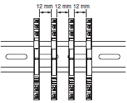
* If the load voltage exceeds 250 VAC, please attach with a spacing of 12 mm min., or use a separate plate (XW5Z-EP12).

Lloyd's (File No.07/10020)
| Model | Contact form | Operation coil ratings | Contact ratings |
|---|---|---|---|
| G2RV-SR500
G2RV-SR700 |
SPDT | 12, 24 VDC
24, 48 VAC/VDC 100, 110, 200, 230 VAC |
6 A at 250 VAC (Resistive load) |
| 2.5 A at 250 VAC (PF0.4) | |||
| 6 A at 30 VAC (Ress) | |||
| 2 A at 30 VDC (L/R=7ms) | |||
| G2RV-SR501
G2RV-SR701 |
SPDT | 12, 24 VDC
24 VAC/VDC |
6 A at 250 VAC (Resistive load) |
| 2.5 A at 250 VAC (PF0.4) | |||
| 6 A at 30 VAC (Ress) | |||
| 2 A at 30 VDC (L/R=7ms) | |||
| G2RV-SR500-AP
G2RV-SR700-AP |
SPDT | 12, 24 VDC
24, 48 VAC/VDC 100, 110, 200, 230 VAC |
0.05 A at 30 VAC (Resistive load)
0.05 A at 36 VDC (Resistive load) |
last update: January 5, 2022
 Product Category
 Relays
-
 General Purpose Relays
-
Discontinued
- G2RV-SR
-
Discontinued
-


