ZP-L
Laser Displacement Sensor
Premium detection stability and optimal usability for Laser Displacement Sensors
Related Contents
last update: February 2, 2026
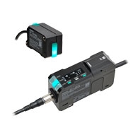
Sensor Head
| Appearance |
Optical
system |
Beam
shape |
Measurement distance |
Resolution
* |
Cable
length |
Model |
|---|---|---|---|---|---|---|

|
Diffuse-
reflective |
Line beam |

|
0.5 μm | 0.2 m | ZP-LS025L 0.2M |
| 2 m | ZP-LS025L 2M | |||||
| Spot beam |

|
0.6 μm | 0.2 m | ZP-LS025S 0.2M | ||
| 2 m | ZP-LS025S 2M | |||||
| Line beam |

|
0.7 μm | 0.2 m | ZP-LS050L 0.2M | ||
| 2 m | ZP-LS050L 2M | |||||
| Spot beam |

|
0.8 μm | 0.2 m | ZP-LS050S 0.2M | ||
| 2 m | ZP-LS050S 2M | |||||
| Line beam |

|
1.2 μm | 0.2 m | ZP-LS100L 0.2M | ||
| 2 m | ZP-LS100L 2M | |||||
| Spot beam |

|
1.3 μm | 0.2 m | ZP-LS100S 0.2M | ||
| 2 m | ZP-LS100S 2M | |||||

|
Diffuse-
reflective |
Line beam |

|
4 μm | 0.2 m | ZP-LS300L 0.2M |
| 2 m | ZP-LS300L 2M | |||||
| Spot beam |

|
4 μm | 0.2 m | ZP-LS300S 0.2M | ||
| 2 m | ZP-LS300S 2M | |||||
| Line beam |

|
14 μm | 0.2 m | ZP-LS600L 0.2M | ||
| 2 m | ZP-LS600L 2M | |||||
| Spot beam |

|
14 μm | 0.2 m | ZP-LS600S 0.2M | ||
| 2 m | ZP-LS600S 2M |
* This shows the width of the variation of measured values when OMRON’s standard target (white diffuse object) is measured at a reference distance with a measurement cycle of 1 ms and an average rate of 128 times.
Note: Sensor heads listed on this data sheet use class 2 lasers, but we offer products with class 1 lasers as well, the model names of which end with the letter “C” followed by cable length (example: ZP-LS025LC 2M).
Amplifier Unit
| Appearance |
Master/
Slave *1 |
Analog
output |
Judgment
output *2 |
External
input *3 |
Input/
output type |
Model |
|---|---|---|---|---|---|---|

|
Master unit | Yes | Yes | Yes | NPN | ZP-L3000 |
| PNP | ZP-L3050 | |||||
| No | Yes | Yes | NPN | ZP-L3010 | ||
| PNP | ZP-L3060 | |||||

|
Slave unit | Yes | Yes | Yes | NPN | ZP-L3500 |
| PNP | ZP-L3550 | |||||
| No | Yes | Yes | NPN | ZP-L3510 | ||
| PNP | ZP-L3560 | |||||

|
Slave unit | No | No | No | ⎯ | ZP-L3590 |
*1. First amplifier unit must be master unit.
In a system with multiple amplifier units connected together, there can only be one master unit.
Power supply connection is required for master unit only. All power supplied to slave and communication units is
supplied from master unit.
*2. HIGH/PASS/LOW
*3. Zero reset, LD-off, timing, reset, bank
IO-Link Compatible Amplifier Unit
| Appearance | Connection method | Analog
output |
Judgment
output *2 |
External
input *3 |
Input/output
type |
Model |
|---|---|---|---|---|---|---|
 |
Discrete wire cable
pull-out type |
No | Yes
(switching) *1 |
Yes
(switching) *1 |
NPN/PNP
(switching) |
ZP-L3930-IL3 |
| M12 connector cable
pull-out type |
NPN/PNP
(switching) |
ZP-L3931-IL3 |
*1. Judgment output and external input can be switched via settings.
*2. HIGH/PASS/LOW
*3. Zero reset, LD-off, timing, reset, bank
Communication Unit
| Appearance | Communication type | Connected devices | Model |
|---|---|---|---|

|
EtherNet/IPTM
No-protocol (TCP) |
PLCs and PCs from
different manufacturers |
ZP-EIP |

|
RS-232C | PLCs and PCs from
different manufacturers |
ZP-RSA |
To use support software Wave Inspire ZP connect your sensor to your PC using the communication unit.
Wave Inspire ZP can be downloaded for free from the URL below.
https://www.ia.omron.com/zp_tool
Wave Inspire ZP is a setup support tool. Please note the following before use.
(1) OMRON assumes no responsibility for damage caused by any malfunctioning of this software, whether directly or
indirectly, or caused by the effects of such malfunctioning.
(2) OMRON assumes no responsibility for any damage incurred by the customer due to use of this software.
Accessories (sold separately)
Sensor head - amplifier unit extension cable
|
Cable
specifications |
Cable connection
direction |
Cable
length |
Model |
|---|---|---|---|
| Normal cable | Amplifier unit side: Straight
Sensor head side: Straight |
1 m | XS3W-M421-401-R |
| 2 m | XS3W-M421-402-R | ||
| 5 m | XS3W-M421-405-R | ||
| 10 m | XS3W-M421-410-R | ||
| 20 m | XS3W-M421-420-R | ||
| Amplifier unit side: L-shaped
Sensor head side: L-shaped |
1 m | XS3W-M422-401-R | |
| 2 m | XS3W-M422-402-R | ||
| 5 m | XS3W-M422-405-R | ||
| 10 m | XS3W-M422-410-R | ||
| 20 m | XS3W-M422-420-R | ||
| Amplifier unit side: Straight
Sensor head side: L-shaped |
1 m | XS3W-M423-401-R | |
| 2 m | XS3W-M423-402-R | ||
| 5 m | XS3W-M423-405-R | ||
| 10 m | XS3W-M423-410-R | ||
| 20 m | XS3W-M423-420-R | ||
| Amplifier unit side: L-shaped
Sensor head side: Straight |
1 m | XS3W-M424-401-R | |
| 2 m | XS3W-M424-402-R | ||
| 5 m | XS3W-M424-405-R | ||
| 10 m | XS3W-M424-410-R | ||
| 20 m | XS3W-M424-420-R | ||
| Robot cable | Amplifier unit side: Straight
Sensor head side: Straight |
1 m | XS3W-M421-401-PR |
| 2 m | XS3W-M421-402-PR | ||
| 5 m | XS3W-M421-405-PR | ||
| 10 m | XS3W-M421-410-PR | ||
| 20 m | XS3W-M421-420-PR | ||
| Amplifier unit side: L-shaped
Sensor head side: L-shaped |
1 m | XS3W-M422-401-PR | |
| 2 m | XS3W-M422-402-PR | ||
| 5 m | XS3W-M422-405-PR | ||
| 10 m | XS3W-M422-410-PR | ||
| 20 m | XS3W-M422-420-PR | ||
| Amplifier unit side: Straight
Sensor head side: L-shaped |
1 m | XS3W-M423-401-PR | |
| 2 m | XS3W-M423-402-PR | ||
| 5 m | XS3W-M423-405-PR | ||
| 10 m | XS3W-M423-410-PR | ||
| 20 m | XS3W-M423-420-PR | ||
| Amplifier unit side: L-shaped
Sensor head side: Straight |
1 m | XS3W-M424-401-PR | |
| 2 m | XS3W-M424-402-PR | ||
| 5 m | XS3W-M424-405-PR | ||
| 10 m | XS3W-M424-410-PR | ||
| 20 m | XS3W-M424-420-PR |
Note: You cannot use multiple extension cables connected together.
<Key points in selecting your extension cable>
• The pre-wired cable of the sensor head is a standard cable. In cases where cable bending is necessary, connect an extension robot cable, and bend the extension cable. We recommend you use a 0.2-m cable for your sensor head.
• Using the L-shaped cable connector for amplifier unit connection allows you to secure space around the area of connection.
Mounting bracket
For ZP-LS025/-LS050/-LS100
| Appearance | Illustration of installed bracket | Model |
|---|---|---|
L-shaped Mounting Bracket
 |

|
ZP-XL1 |
Rear Mounting Bracket
 |

|
ZP-XL2 |
Flexible Mounting Bracket
 |

|
ZP-XL5 |
Post 50 mm
 |
E39-L262 | |
Post 100 mm
 |
E39-L263 |
For ZP-LS300/-LS600
| Appearance | Illustration of installed bracket | Model |
|---|---|---|
L-shaped Mounting Bracket
 |

|
ZP-XL3 |
Rear Mounting Bracket
 |

|
ZP-XL4 |
Flexible Mounting Bracket
 |

|
ZP-XL6 |
Post 50 mm
 |
E39-L262 | |
Post 100 mm
 |
E39-L263 |
Recommended EtherNet/IP Communications Cables
For EtherNet/IP, required specification for the communications cables varies depending on the baud rate. For 100BASE-TX/10BASE-T, use a straight or cross STP (shielded twisted-pair) cable of category 5 or higher.
Cable with Connectors
| Item |
Recommended
manufacturer |
Cable
length (m) |
Model | |
|---|---|---|---|---|
| Wire gauge and
number of pairs: AWG26, 4-pair cable Cable sheath material: PUR |
Cable with Connectors
on Both Ends (RJ45/RJ45) Standard RJ45 plugs *1 Cable color: Yellow *2 EtherNet/IP (10BASE/100BASE)  |
OMRON | 0.3 | XS6W-6PUR8SS30CM-YF |
| 0.5 | XS6W-6PUR8SS50CM-YF | |||
| 1 | XS6W-6PUR8SS100CM-YF | |||
| 2 | XS6W-6PUR8SS200CM-YF | |||
| 3 | XS6W-6PUR8SS300CM-YF | |||
| 5 | XS6W-6PUR8SS500CM-YF | |||
| Cable with Connectors
on Both Ends (RJ45/RJ45) Rugged RJ45 plugs *1 Cable color: Light blue EtherNet/IP (10BASE/100BASE)  |
0.3 | XS5W-T421-AMD-K | ||
| 0.5 | XS5W-T421-BMD-K | |||
| 1 | XS5W-T421-CMD-K | |||
| 2 | XS5W-T421-DMD-K | |||
| 5 | XS5W-T421-GMD-K | |||
| 10 | XS5W-T421-JMD-K | |||
*1. Cables with standard RJ45 plugs are available in the following lengths: 0.2 m, 0.3 m, 0.5 m, 1 m, 1.5 m, 2 m, 3 m,
5 m, 7.5 m, 10 m, 15 m, 20 m.
Cables with rugged RJ45 plugs are available in the following lengths: 0.3 m, 0.5 m, 1 m, 2 m, 3 m, 5 m, 10 m, 15 m.
For details, refer to the Industrial Ethernet Connectors Catalog (Cat. No. G019).
*2. Cable colors are available in yellow, green, and blue.
Cables/Connectors
| Item |
Recommended
manufacturer |
Model | ||
|---|---|---|---|---|
| Products for
EtherNet/IP (100BASE-TX/ 10BASE-T) |
Wire gauge and
number of pairs: AWG22, 2-pair cable |
Cable | Kuramo Electric Co. | KETH-PSB-OMR *1 |
| JMACS Japan Co., Ltd. | PNET/B *1 | |||
| RJ45 Assembly
Connector  |
OMRON | XS6G-T421-1 *1 | ||
*1. We recommend you to use the above Cable and RJ45 Assembly Connector together.
last update: February 2, 2026