Discontinued On Mar. 2021
MS4800 Series
Safety Light Curtain
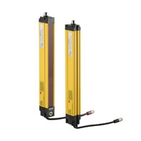
Safety Light Curtains with Durable, Impact-resistant Body and Long, 20-m Sensing Distance
* Information in this page is a reference that you created on the basis of information in the product catalog before the end of production, may be different from the current situation, such as goods for / supported standards options / price / features of the product. Before using, please check the compatibility and safety system.
Related Contents
- Features
- Lineup
- Specifications
- Dimensions
- Catalog / Manual / CAD / Software
last update: September 24, 2012
Safety Light Curtains
MS/MSF4800-series Safety Light Curtains
| Series | Advanced Series | Basic Series | |||
|---|---|---|---|---|---|
| Model | Individual
use |
MS4800A-30-[] | MS4800A-40-[] | MS4800B-30-[] | MS4800B-40-[] |
| Series
connection |
MSF4800A-30-[] | MSF4800A-40-[] | MSF4800B-30-[] | MSF4800B-40-[] | |
| Sensor type | Type 4 Safety Light Curtain | ||||
| Setting tool connection | Connectable | ||||
| Applicable safety category | Category 4, 3, 2, 1, or B | ||||
| Minimum detectable object | Opaque object:
30-mm dia. |
Opaque object:
40-mm dia. |
Opaque object:
30-mm dia. |
Opaque object:
40-mm dia. |
|
| Beam gap (P) | 20 mm | 30 mm | 20 mm | 30 mm | |
| Number of beams (n) | 14 to 106 | 12 to 68 | 14 to 106 | 12 to 68 | |
| Protective height (PH) | 280 to 2120 mm | 360 to 2040 mm | 280 to 2120 mm | 360 to 2040 mm | |
| Sensing distance *1 | 0.3 to 20 m (selectable from 0.3 to 8 m with the Programming and Diagnostics
Module) |
||||
| Lens diameter | Diameter 7 mm | ||||
| Response time
(under stable light incident condition) (Refer to Response Time below for details.) |
ON to OFF | Individual:
14 to 32 ms |
Individual:
14 to 23 ms |
Individual:
14 to 32 ms |
Individual:
14 to 23 ms |
| OFF to ON | 320 ms max. | ||||
| Startup waiting time | 3.5 s max. for individual use, 4.5 s max. for series connection | ||||
| Power supply voltage (Vs) | 24 VDC ±20% (ripple p-p: 5% max.) | ||||
| Current
consumption *2 (no load) |
Transmitter | 285 mA max. | |||
| Receiver | 450 mA max. | ||||
| Light source (emitted
wavelength) |
Infrared LEDs (wavelength: 880 nm) | ||||
| Effective aperture angle (EAA) | Within ±2.5° for the Transmitter and Receiver at a sensing distance of at least 3 m
according to IEC 61496-2. |
||||
| Control output (OSSD) *3 | Output transistor: PNP × 2, Load current: 625 mA max. (at 24 VDC), short-circuit
protection |
||||
| Auxiliary output *3
(non-safety output) |
Output transistor:
PNP × 1 or NPN × 1, selectable with the Programming and Diagnostics Module, Load current: 100 mA max. (at 24 VDC) Output mode: Control output synchronizing or alarm is selectable with the Programming and Diagnostics Module |
Output transistor:
PNP × 1, Load current: 100 mA max. (at 24 VDC) Output mode: Control output synchronizing |
|||
| Output operation mode | Control output 1, 2: Light-ON
Auxiliary output: Control Output Synchronizing Mode: Auxiliary output goes ON when control output goes ON Alarm Mode: Auxiliary output goes ON when the MS4800 enters alarm (lockout) condition |
||||
| Input voltage | External device monitoring input ON voltage: 11 to 28.8 V, OFF voltage: 0 to 2.6 V
Start input ON voltage: 11 to 28.8 V, OFF voltage: 0 to 1.2 V For the MS4800B, use NC contacts for the start input switch. For the MS4800A, refer to Start Input Methods (MS/MSF4800A Only) on Data Sheet. |
||||
| Internal
indicators |
Transmitter | Transmitter Indicator (Yellow): Indicator is ON when transmitting | |||
| Receiver | Blanking Indicator (Orange): Indicator is ON in Blanking Active State
Interlock or Alarm (Lockout) Indicator: Indicator is ON in Interlock State, and indicator flashes in Alarm (Lockout) State Machine Run/Stop Indicator (Green/Red): Green indicator is ON when Control Output is ON, and red indicator is ON when Control Output is OFF |
||||
| Mutual interference
prevention function |
The scan code (A/B) can be switched with the Programming and Diagnostics Module | ||||
| Series connection | MSF4800 only
• Connectable segments: 4 max. • Total number of beams: 256 max. • Maximum cable length between segments: 10 m • Response time when connected: Refer to Data Sheet. |
||||
| Test functions | • Self test (when power is turned ON and while power is supplied)
• External test (light emission stop function by test input) |
||||
| Safety functions | • Selection of auto start mode and
interlock mode • External device monitoring • Muting (MSF4800A only) (MS4800-RM6 (sold separately) is required.) • Fixed blanking • Floating blanking • Monitored blanking • Reduced resolution blanking |
• Selection of auto start mode and
interlock mode • External device monitoring |
|||
| Connection method | Power supply connectors (M12, Transmitter: 5-pin, Receiver: 8-pin)
Series-connection connectors: (M12, Transmitter: 4-pin, Receiver: 4-pin) |
||||
| Protective circuit | Output short-circuit protection, reverse polarity protection | ||||
| Ambient temperature | Operating: -10 to 55°C (with no icing), storage: -25 to 70°C | ||||
| Ambient humidity | 95% max. (with no condensation) | ||||
| Insulation resistance | 20 MΩ min. (at 500 VDC) | ||||
| Dielectric strength | Transmitter: 350 VAC 60 Hz 1 min
Receiver: 500 VDC 1 min |
||||
| Degree of protection | IP65 (IEC 60529) | ||||
| Vibration resistance | Malfunction: 10 to 55 Hz, 0.7-mm double amplitude, 20 sweeps in X, Y, and Z
directions |
||||
| Shock resistance | Malfunction: 10G, 1,000 times in X, Y, and Z directions | ||||
| Materials | Case: Aluminum with polyurethane powder coating
Cap: Polycarbonate |
||||
| Weight (packed state) | • MS4800[]-30-[][][][]: Weight (g) = α x Protective height + 349
• MSF4800[]-30-[][][][]: Weight (g) = α x Protective height + 361 • MSF4800[]-30-[][][][]-XR2: Weight (g) = α x Protective height • MS4800[]-40-[][][][]: Weight (g) = α x Protective height + 370 • MSF4800[]-40-[][][][]: Weight (g) = α x Protective height + 382 • MSF4800[]-40-[][][][]-XR2: Weight (g) = α x Protective height The values for α are as follows: For protective height from 240 to 280: 10 For protective height from 320 to 360: 9 For protective height from 400 to 1,080: 8 For protective height from 1,120 to 1,840: 7 For protective height from 1,880 to 2,120: 6 |
||||
| Accessories | Test rod, Instruction Manual, mounting set (2 top, 2 bottom mounting brackets),
surge absorber |
||||
| Applicable standards | IEC 61496-1, EN 61496-1, UL 61496-1 Type 4 ESPE (Electro-Sensitive Protective
Equipment), IEC 61496-2, CLC/TS61496-2, UL 61496-2 Type 4 AOPD (Active Opto-electronic Protective Devices), IEC 61508 SIL3 |
||||
*1. Use of the Spatter Protection Cover causes a 10% maximum sensing distance attenuation.
*2. The consumption current must not exceed 1.35 A for both the control outputs and auxiliary output. The rated current
is the sum of the Transmitter (285 mA), Receiver (450 mA), control output 1 (625 mA), control output 2 (625 mA),
and auxiliary output (100 mA).
*3. The 24-VDC value is a nominal value. The actual voltage depends on the supply voltage. Actual voltage = Supply
voltage − 1 V.
Response Time
Curtains Used Individually (1-segment System)
| Minimum number of beams | Maximum number of beams | Response time (ms) | |
|---|---|---|---|
| Normal | Delayed * | ||
| 0 | 16 | 14 | 23 |
| 17 | 71 | 23 | 38 |
| 72 | 126 | 32 | 53 |
| 127 | 180 | 41 | 68 |
| 181 | 235 | 50 | 83 |
| 236 | 256 | 59 | 99 |
Curtains Used in Series Connection (3-segment System)
| Minimum number of beams | Maximum number of beams | Response time (ms) | |
|---|---|---|---|
| Normal | Delayed * | ||
| 0 | 59 | 23 | 38 |
| 60 | 114 | 32 | 53 |
| 115 | 168 | 41 | 68 |
| 169 | 223 | 50 | 83 |
| 224 | 256 | 59 | 99 |
Curtains Used in Series Connection (2-segment System)
| Minimum number of beams | Maximum number of beams | Response time (ms) | |
|---|---|---|---|
| Normal | Delayed * | ||
| 0 | 65 | 23 | 38 |
| 66 | 120 | 32 | 53 |
| 121 | 174 | 41 | 68 |
| 175 | 229 | 50 | 83 |
| 230 | 256 | 59 | 99 |
Curtains Used in Series Connection (4-segment System)
| Minimum number of beams | Maximum number of beams | Response time (ms) | |
|---|---|---|---|
| Normal | Delayed * | ||
| 0 | 53 | 23 | 38 |
| 54 | 108 | 32 | 53 |
| 109 | 162 | 41 | 68 |
| 163 | 217 | 50 | 83 |
| 218 | 256 | 59 | 99 |
* Refer to Response Time Adjustment (MS/MSF4800A Only) on Data Sheet.
Cable Extension Length
The maximum length and wire gauge for input and output signals are given in the following table.
| Type | Signal name | Wire gauge | Rated maximum length |
|---|---|---|---|
| Receiver | Control outputs 1 and 2 | 22 AW G (0.32 mm) | 300-mA load: 45 m, 625-mA load: 22 m |
| Auxiliary output | 22 AW G (0.32 mm) | 50 m | |
| Start input | 24 AW G (0.20 mm) | 50 m | |
| External device monitoring (EDM) input | 24 AW G (0.20 mm) | 50 m | |
| +24 V, 0 V | 20 AW G (0.52 mm) | 1.8-A load: 12.5 m, 1-A load: 22 m | |
| Transmitter | +24 V, 0 V | 22 AW G (0.32 mm) | 0.3-A load: 47 m |
| Machine test signal (MTS) | 22 AW G (0.32 mm) | 50 m |
Note: Keep the cable length within the rated length. Failure to do so is dangerous because it may prevent safety functions
from operating normally.
from operating normally.
Accessories
Resource Module
| Model | MS4800-RM6 |
|---|---|
| Input power supply | 24 VDC ± 20%, 30 mA max. |
| Ambient temperature | 0 to 55 ° C |
| Ambient humidity | 95% max. (with no condensation) |
| Storage temperature | - 25 to 75 ° C |
| Vibration resistance | Malfunction: 10 to 55 Hz, 0.7-mm double amplitude, 20 sweeps in X, Y, and Z directions |
| Shock resistance | Malfunction: 10G, 1,000 times in X, Y, and Z directions |
| Degree of protection | IP2 0 (IEC 60529) |
| Muting sensor | PNP 24-VDC (power consumption: 20 mA) Dark-ON/Light-ON or NO/NC combination |
| Muting indicator output * | 10 to 100 mA (NPN), 30 VDC max. |
| Applicable safety category | IEC 61496-1 Type 4 |
*1. For details, refer to Mini Safe 4800 Series Light Curtains Installation and Operating Manual.
*2. The muting indicator output contains a current monitoring circuit to confirm normal operation. Connect an external
indicator load that supplies 10 to 100 mA of current.
*2. The muting indicator output contains a current monitoring circuit to confirm normal operation. Connect an external
indicator load that supplies 10 to 100 mA of current.
Programming and Diagnostics Module
| Model | MS4800-PDM |
|---|---|
| Display | LCD multi-line display |
| Language capability | English, Japanese |
| Degree of protection | Conforms to IP65 |
last update: September 24, 2012
 Product Category
- Safety Components
-
Safety Light Curtains / Safety Multi-Light Beams / Single-beam Safety Sensors
-
Discontinued
- MS4800 Series
-
Discontinued
-